Welcome to Matrix Education
To ensure we are showing you the most relevant content, please select your location below.
Select a year to see courses
Select a year to see available courses
In this article, we’re going to break down electromagnetism from first principles so you understand the basic concepts and how it can be applied practically in a motor.
Charge up your Physics marks!
Get the competitive edge for your next Physics assessment! 
Download your FREE foldable Physics Cheatsheet
In Year 11, you learned about electric and magnetic fields and analysed the behaviour of electrical circuits. However, James Clerk Maxwell demonstrated in the late 19th century that electricity and magnetism could be described as aspects of a single phenomenon: electromagnetism.
In Year 12 we examine how charges respond to both types of fields and use our knowledge to understand how electrical devices such as motors, generators and transformers work.
The module can be divided into three major areas:
There’s also the possibility that you’ll need to build a motor, too.
In Year 11, you’ve already learned about forces on charged particles in electric fields. Recall that the force is given by
\( \overrightarrow{F}=q \overrightarrow{E}\)
where \(q\) is the charge in coulombs and \(E\) is the electric field strength in \(\frac{N}{C}\). The direction of the force depends on the charge. Positive charges experience a force in the direction of the field lines, whereas negative charges experience a force in the opposite direction.
To simplify questions, constant electric fields are often used. These are created by applying a voltage \(V\) between two parallel metal plates separated by a distance \(d\), which gives a uniform field between the plates of magnitude
\( E =\frac{V}{d}\).
A charge between the plates will experience a constant acceleration given by
\(a=\frac{F}{m}=\frac{q}{m} \ E\).
The trajectory of the particle will be similar to projectile motion as you only have acceleration in one direction (down in the case of projectile motion, and in the direction of the electric force in the case of an electric field).
A charge moving through the electric field between two parallel plates will have the electric force continually acting on it, meaning this force will do work. The work can be expressed in various ways and will affect the particle’s kinetic energy:
\(W=\Delta K=qV=qEd\).
In this module, we also consider how charges respond to magnetic fields. The magnitude of the magnetic force on a moving charge is:
\(F=qv_{\perp} B=qvB \sin \theta\)
where \(q\) is the charge, \(v\) is the speed in \(\text{ms}^{-1}\), \(B\) is the magnetic field strength in tesla and \(\theta\) is the angle between the particle’s velocity and the direction of the magnetic field.
Note that this equation tells us two important things: a stationary particle experiences zero force, as does a particle travelling parallel to the magnetic field lines.
Give you marks the last-minute push they need. The Matrix+ Physics HSC prep course provides you with one-to-one feedback and expert help. Learn more.
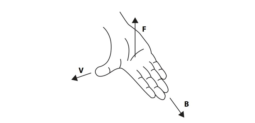
In order to determine the direction of the magnetic force, we use the right-hand palm rule. The thumb points in the direction of a positive particle’s velocity. The fingers point in the direction of the magnetic field lines. The direction in which your palm “pushes” is the direction of the force on a positively charged particle.
If you are travelling at some angle \(0° < \theta < 90°\) to the field, then consider how the velocity component perpendicular to the field would be affected.
As the force is of a constant magnitude and always perpendicular to the velocity, the speed of the particle remains constant but velocity changes direction at a constant rate. This results in uniform circular motion, where the centripetal force is provided by the magnetic force:
\(qvB=\frac{mv^2}{R}\)
for \(R\) the radius of the circular path.

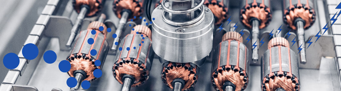
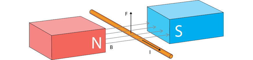
The force on single charges can be extended to currents. By definition, a current-carrying wire contains a large number of charges all moving in the same direction with the same velocity! This will result on a force on a current-carrying conductor placed in a magnetic field – a phenomenon referred to as the motor effect.
The magnitude of this force is given by:
\(F=lI_{\perp} B=lIB \sin \theta\)
where \(l\) is the length of wire inside the field in metres, \(I\) is the current in amperes, \(B\) is the magnetic field strength and \(\theta\) is the angle between the current vector and the field lines. We see that if the current is parallel to the field then there is no force, which matches what we saw in Section 1. The direction of the force is found by the same right-hand rule as Section 1, where your thumb now points in the direction of the current (which would be the same as the velocity of positive charges forming the current).
Recall from Year 11 that current-carrying wires also generate their own magnetic fields. This means that if two wires are parallel to each other, they will each experience a force from each other’s magnetic field due to the motor fact. This strength of this force is given by Ampere’s Law, which tells us that the force per unit length \(\frac{F}{l}\) is:
\(\frac{F}{l}=\frac{μ_0}{2\pi} \frac{I_1 I_2}{r}\)
where \(I_1\) and \(I_2\) are the two currents, r is the distance between the two wires, and \(μ_0\) is the permeability of free space (\(μ_0=4 \pi \times 10^{-7} \text{ NA}^{-2}\)).
The motor effect is the basis for an electric motor – a device which takes electrical energy and converts it to kinetic energy. To understand how, start by considering a conducting loop placed inside a magnetic field, as in the diagrams below (the lower diagram shows a cross-section of the loop).
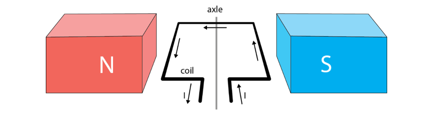

On one side, the current is flowing into the page and on the other side, it is flowing out of the page.
There will be a force on each side of the loop. The forces are in opposite directions, but both lead to a torque in the same direction – clockwise in this case – and so the loop begins to rotate.
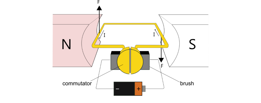
To ensure it rotates continuously in one direction, we need the current on the left-hand side of the diagram above to always be out of the page, and the current on the right hand side to always be into the page. This will keep the forces in the directions shown above, and the torque clockwise. To achieve this, we add a split-ring commutator which switches the electrical contacts every half-turn and ensures the torque is always in the same direction. The electrical contacts are called brushes, and maintain contact between the commutator (which is on the rotating part of the motor – the rotor) and the power supply.
The torque produced by the forces on the coil in a motor like the one above is given by
\( \tau = nIA_ {\bot} B = nIAB \sin \theta \)
Where \(N\) is the number of turns in the coil, \(I\) is the current flowing through it, \(A\) is the area of the coil, \(B\) is the magnetic field the coil experiences, and \(\theta\) is the angle between the normal to the coil and the magnetic field lines.
So far in your studies, you have seen that in order for a current to flow in a circuit, we must connect it to a source of potential difference such as a battery.
There is an alternative, which relies on the relationship between electricity and magnetism: we can use changes in magnetic flux in order to induce an electromotive force (EMF) and (if the circuit is closed) a current.
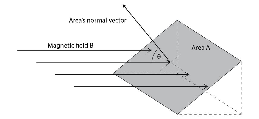
Magnetic flux \(\Phi\) essentially measures a “total amount” of magnetic field contained within a certain area, \(A\). It can be thought of as the total number of enclosed field lines, while magnetic field strength \(B\) is the density of those lines.
Mathematically:
\(\Phi=B_{∥} A=BA\cos\theta\)
where \(B\) is the magnetic field strength, \(A\) is the area and \(\theta\) is the angle between the field lines and the normal vector to the area. Magnetic flux is measured in weber (\(Wb\)) or tesla metres squared (\(\text{Tm}^2\)).
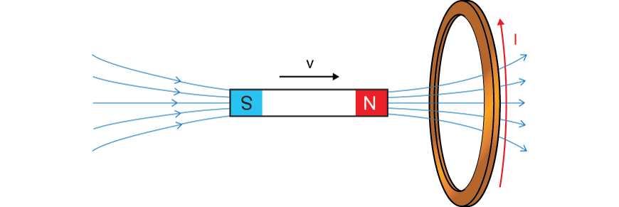
Michael Faraday discovered that when the flux passing through a conducting loop changes, an electromotive force (EMF) is induced. This is known as Faraday’s Law and it can be written mathematically:
\(\epsilon= -N \frac{\Delta\Phi}{\Delta t}\)
Note that \(N\) is the number of loops experiencing a change in flux, e.g. in a solenoid. The change in flux can be due to changes in \(B\), \(A\), \(θ\), or any combination of these. The EMF can result in a charge separation and a voltage, and if the loop forms a closed circuit, in a current. The size of the current depends on the resistance of the circuit and follows Ohm’s Law:
\(I=\frac{V}{R}\)
What is the meaning of the negative sign in Faraday’s Law? The answer is expressed by Lenz’s law, which states that the induced EMF (and current) will be in such a direction that the flux it creates will oppose the change in flux that caused it.
For example, if you try to increase flux into the page through a loop, it reacts by creating its own flux out of the page – to oppose the increase. If you try to decrease flux into the page, it reacts by creating its own flux into the page – to oppose the decrease.
Lenz’s law gives the direction of the induced EMF and the induced current (if there is one). Lenz’s law will also result in an opposing force, which is most useful in cases where the change in flux causing induction was caused by motion. For example, if the flux through a coil increases because a magnet is moving closer to it, induction will result in a force opposing the motion of the magnet.
Induction has many uses: it is the principle behind a generator, transformers, wireless chargers and the AC induction motor.
A generator is structurally the same as a motor, however the coil is manually rotated and experiences a change in flux as a result. This leads to an induced EMF and current through Faraday’s and Lenz’s laws, which is the generated electricity.
The current generated by the rotating coil is always AC. A DC generator can be made using an identical structure to a DC motor, where the split ring commutator will convert the AC induced in the coil to DC in the external circuit. An AC generator can be made by replacing the commutator with two slip rings – each slip ring is connected to one side of the coil, and only one brush, and conducts the AC through to the external circuit.
A transformer is a device used to convert an AC input voltage to a different output voltage, which can be higher (step-up transformer) or lower (step-down transformer).
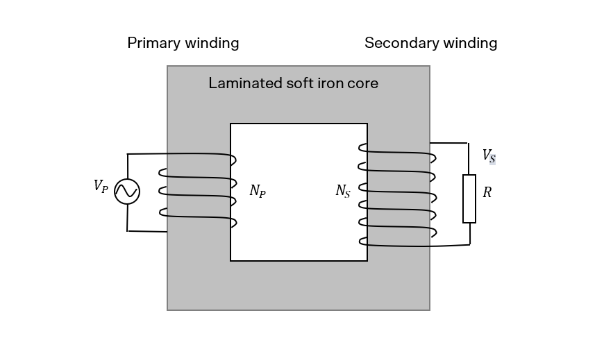
The alternating current in the primary winding results in a constantly varying magnetic flux being produced. The secondary winding experiences this changing flux and as a result of Faraday’s and Lenz’s laws there will be an EMF (voltage) and current induced in the secondary winding.
The voltages in each winding are related by the following equation:
\(\frac{V_p}{V_s} =\frac{N_p}{N_s}\)
According to conservation of energy, an ideal transformer will transmit 100% of the power in the primary to the secondary such that:
\(V_pI_p=V_sI_s\).
Induction can also be used to explain the operation of induction motors. Unlike the DC motor discussed earlier, the rotor (the central part that rotates) in the AC induction motor is not directly supplied with current. Instead we use electromagnetic induction to induce current flow in the rotor.
A three-phase AC power supply is used to power coils in the stator (the outer stationary part) of the induction motor. This effectively creates a rotating magnetic field. The rotor sits inside this field and experiences a change in flux. Following Faraday’s and Lenz’s laws, current is induced in the rotor, which in turn results in forces and torque, and it begins to rotate in the same direction as the field.
Electromagnetic induction occurs in solid conductors as well as loops. In solid conductors the induced currents flow in a circular path and are called ‘eddy currents’. These are often unwanted, as they dissipate electrical energy in the form of heat e.g. in the core of a transformer. However, there are cases where this energy dissipation is useful, such as in electromagnetic braking, where the opposing force from Lenz’s law provides the braking force.
Another unwanted example of induction is in DC motors. As the coil of the motor rotates in the magnetic field, it experiences a changing magnetic flux just like the coil in a generator. Induction opposes the change that caused it, so the induced EMF is in the opposite direction to the voltage that’s powering the motor and is called back EMF. The back EMF reduces the total voltage and current on the coil and hence reduces the torque causing rotation.
You can put this into practice when you build a DC motor. If you’d like to know more about the practical application of this theory, you should check out these two articles:
© Matrix Education and www.matrix.edu.au, 2025. Unauthorised use and/or duplication of this material without express and written permission from this site’s author and/or owner is strictly prohibited. Excerpts and links may be used, provided that full and clear credit is given to Matrix Education and www.matrix.edu.au with appropriate and specific direction to the original content.