Welcome to Matrix Education
To ensure we are showing you the most relevant content, please select your location below.
Select a year to see courses
Select a year to see available courses
In this post, Physicist Tom Dixon shares the top 5 mistakes he sees students make when building motors and how to fix them.

Join 75,893 students who already have a head start.
"*" indicates required fields

Join 8000+ students each term who already have a head start on their school academic journey.
Is your motor all powered up, but not spinning? Don’t worry! In this article, Experimental Physicist and Matrix Physics guru Tom Dixon shares the top 5 student mistakes when building electric motors.
Tom explains the theory, describes the problem and then provides simple solutions so that you can motor through your next HSC Physics Practical Assessment.
The connection between the commutator and brushes allows current to be supplied to the motor, and for that current to reverse direction every half turn.
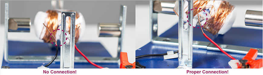
Most students will use bare wires as their brushes. If the wires are not pressing strongly enough against the commutator, they will not be in electrical contact for the entire rotation!
Connect an ammeter in series with the motor and rotate the coil 360 degrees – check if current is flowing throughout the rotation. There should be electrical connection almost constantly.
Using a rigid wire will ensure that they are not pushed away from the commutator during rotation. In addition, using the middle of the bare-part of the wire (not the tip) for the contact can make for a smoother connection.
In the rotor, each side of the commutator is attached to one end of the coil. Power is connected to the commutator (via the brushes) and then into the coil.
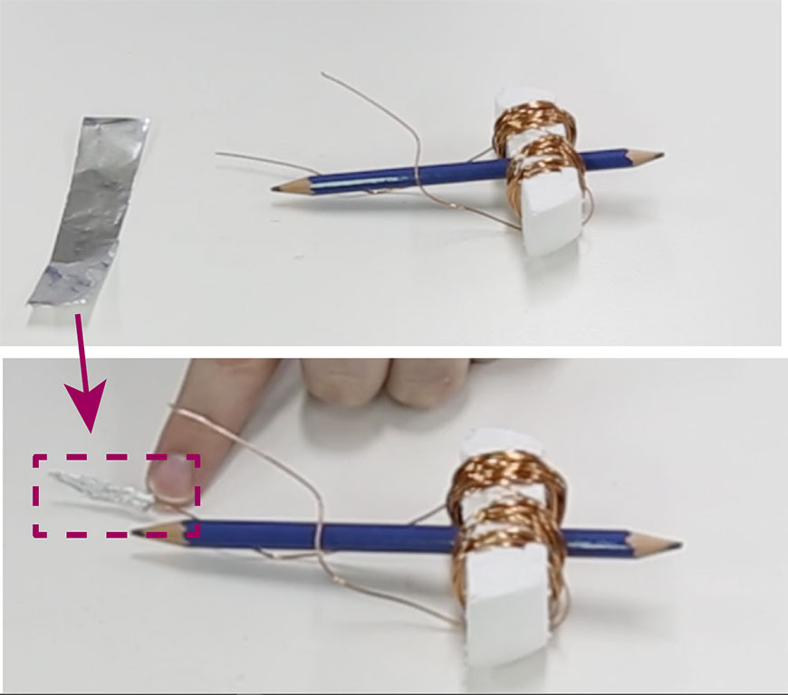
Students may not have properly stripped the insulation from the edges of their wire; the commutator might not be connected to the underlying coil wires!
Check the connection between the two ends of the coil before constructing the commutator (you can use a multimeter in ‘beep mode’). You can improve the connection by wrapping the bare copper ends in aluminium foil before constructing the commutator.
The motor generates a torque that rotates the rotor. Sources of friction in the motor will oppose this motion, reducing the net torque slightly.
In some motor constructions, the frictional torque is greater than the motor torque! This will result in a motor that doesn’t move, or only makes it a few turns before stopping.
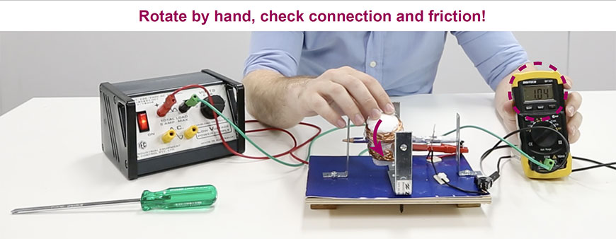
Reducing friction is necessary – check the rotor mounting points and see if you can make the connection smoother. Also consider the connection between the brushes and commutator – if they are pressing too hard, this will be another source of friction.
It is always a good idea to spin the motor by hand, to see if there are any points in its rotation where it catches / experiences a lot of resistance.
Get ahead of your peers with our Year 12 Physics Matrix Course. With advanced completion of contents before it’s taught at school, you’ll be better prepared for your school assessments. Learn more about Year 12 Physics.
Due to the relative motion between commutator and brushes, there is quite a bit of friction. In conventional motors, this wears away the commutator brushes, which are easy to replace.
If students build the commutator out of a weak material like aluminium foil, it will likely wear away first due to friction between the brush-wires and the foil. This can lead to poorer electrical contact and the motor not working!
In a pinch, you can always add more foil to each side of the commutator, if you make sure that the separate sides still don’t touch. A better long-term solution is to use thin, malleable sheet metal like copper sheet, which you can get from an arts and crafts store – these are far likely to last when compared to aluminium foil!
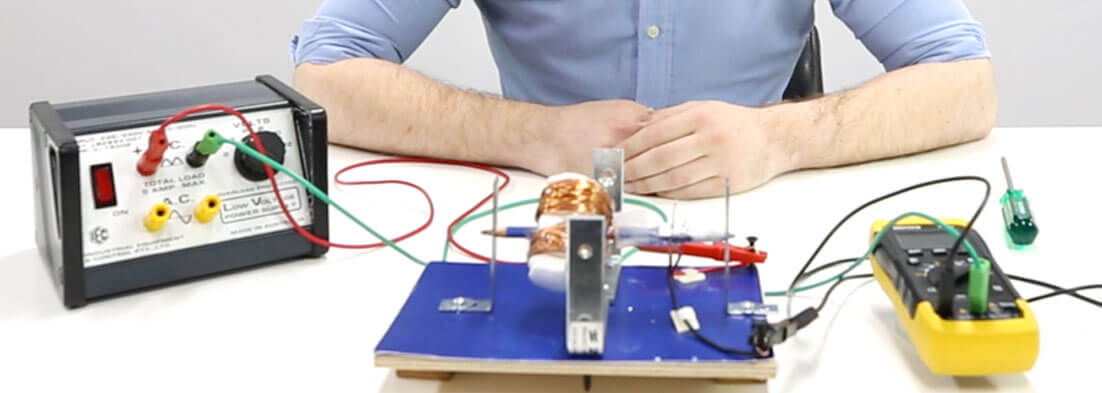
The rotor is supported in two places by the rotor mounts – usually at either ends of the rotor.
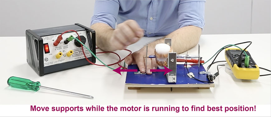
If the two rotor mounts are slightly misaligned, the rotor may jam, or experience a high amount of friction. Unfortunately, it is difficult to know if the alignment of the rotor mounts is at the best position until you turn on the motor!
One possible solution is to leave one rotor mount loose and able to be re-positioned. Then, you can re-position the mount as the motor is running, moving it around until you find the best configuration.
Download the Matrix Practical Skills Workbook and sharpen your Physics skills. Learn how to:
Written by Tom Dixon
Dr. Thomas Dixon is an Associate Lecturer (Education Focused) in the School of Physics, and teaches HSC Physics at Matrix Education. His passion for Physics communication and education has impacted thousands of Science students in secondary schools and at the university level over the past 10 years!© Matrix Education and www.matrix.edu.au, 2025. Unauthorised use and/or duplication of this material without express and written permission from this site’s author and/or owner is strictly prohibited. Excerpts and links may be used, provided that full and clear credit is given to Matrix Education and www.matrix.edu.au with appropriate and specific direction to the original content.