Welcome to Matrix Education
To ensure we are showing you the most relevant content, please select your location below.
Select a year to see courses
Select a year to see available courses

Want to get ahead for the next term in Electricity and Magnetism? Well, in this article, we will break down electrostatics, electric circuits and magnetism to help you prepare and ace Module 4!
Charge up your Physics marks!
Get the competitive edge for your next Physics assessment! 
Download your FREE foldable Physics Cheatsheet
In this article, we’ll look at the following topics:
There are four fundamental forces in the universe and one of them is electromagnetism.
It is the force that determines the behaviour of charges.
However, before we study it in its full form (Year 12, Module 6) we need to separately develop our understanding of electricity and magnetism.
Charge comes in two types: positive and negative.
The unit of charge is the coulomb, written as \( \text{C} \) .
Whenever we have an equal amount of both types, we refer to the state as being neutral.
Two charges of the same sign will always repel each other, while opposite charges will always attract each other.
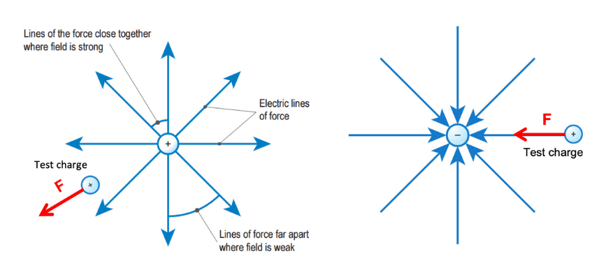
Any charged object produces an electric field, which we can represent using field lines.
The lines point in the direction of the force that would be exerted on a positive test charge, and the line density represents the strength of the field.
Electric field strength \( E \) is expressed in units of newtons per coulomb, or \( \text{NC}^{-1} \) .
If the strength of the field is known, the force on a charge inside that field can be calculated via:
\begin{align*}
F \ = \ qE
\end{align*}
Where:
The force will be in the same direction as a field line if the charge is positive, and in the opposite direction if the charge is negative.
If the electric field varies as it does around a single charge, we cannot assume the value of \( E \) at any point.
Instead, we use Coulomb’s Law for the force between two charges.
\begin{align*}
F \ = \ \frac{1}{4 \pi \varepsilon _{0}} \ \frac{q_{1}q_{2}}{r^{2}}
\end{align*}
Where:
Like many laws of physics, Coulomb’s Law is an inverse square law: the force decreases in proportion to \( 1/r^{2} \) .
It is possible to create a uniform electric field with constant strength and direction with the use of conducting parallel plates. When they are connected to a battery, the plates become oppositely charged and a field forms.
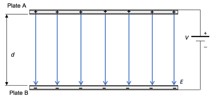
The arrangement pictured creates an electric field with strength
\begin{align*}
E = \frac{V}{d}
\end{align*}
Where:
Let us consider the meaning of potential difference.
If a positive charge is placed in the field between two plates near the positive plate, there is a downwards force due to the electric field and hence the charge accelerates downwards; described another way, the field will do work on it to increase its kinetic energy.
The kinetic energy must come from somewhere in order to conserve energy, so the charge loses electrical potential energy.
However, the value of this quantity depends on the sign and magnitude of the charge involved.
A more useful quantity is the electrical potential (also known as voltage) – the work done per unit charge.
For example, passing through a potential difference of \( 1.5 \text{ V} \) is equivalent to \( 1.5 \text{ J} \) of work done per coulomb of charge.
Take advantage of your school holidays and get ahead in Physics with our Matrix Holiday Course. Our HSC Expert teachers will break down the content, and provide you with practice questions to help you prepare for Electricity and Magnetism! Learn more now.
An electric circuit uses moving charges to transfer electrical energy from a power supply such as a battery to the devices in your home, including lamps, heaters and appliances.
In Year 11, we focus on DC or ‘direct current’ circuits, where charges flow in one direction around an entire circuit.
When a significant amount of charge moves through a conductor together, we call it an electric current.
This is measured in amperes \( (\text{A}) \), a unit defined as the number of coulombs passing a point every second.
We now know that charge is carried by electrons, but since electrical current was discovered before any subatomic particles, we use the established convention that positive charge flows around a circuit.
This is referred to as conventional current. If a question requires you to describe the motion of electrons, it will specify ‘electron flow’ or something similar.
We imagine positive charges leaving the positive terminal of a DC power supply with a certain amount of electrical potential energy, which is converted to other forms as the charges travel towards the negative terminal.
We use voltage to express a quantity of the work each charge can do as it travels around the circuit. As noted above, one volt \( (1 \text{ V}) \) is equivalent to one joule per coulomb \( (1 \text{ JC}^{-1}) \).
Charges encounter some opposition to their flow as they travel, which we quantify as electrical resistance, measured in units of ohms \( (Ω) \).
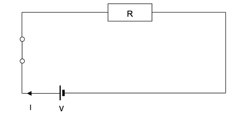
Finally, we can relate the voltage of the power supply to the current that will flow using Ohm’s Law:
\begin{align*}
I \ = \ \frac{V}{R}
\end{align*}
Where:
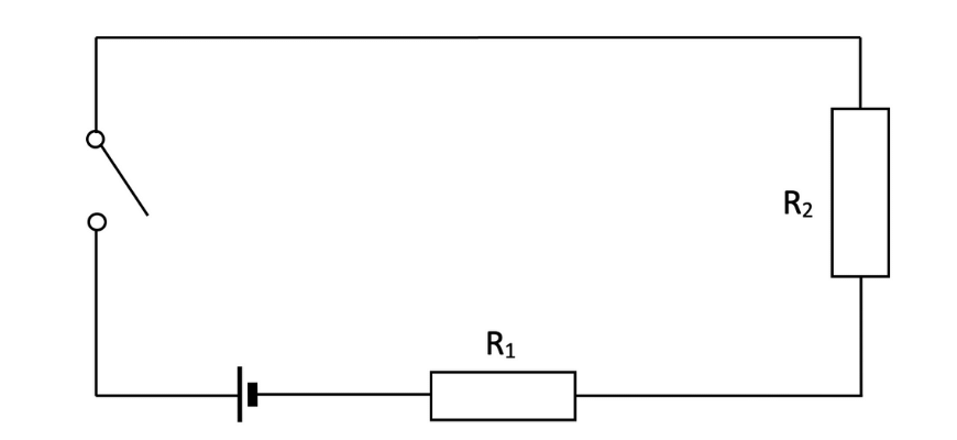
If there are multiple resistances in a circuit, we can combine their effects into a single ‘equivalent’ resistor.
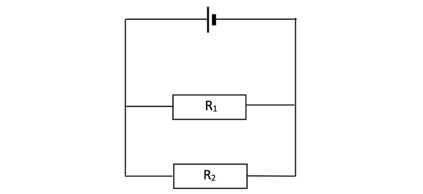
The method for doing this depends on how the resistors are connected to each other – whether they are in series, with charges passing through each one in sequence, or in parallel, with charges travelling across different mutually exclusive paths.
\begin{align*}
R_{series} \ = \ R_{1} \ + \ R_{2} \ + \ … \ + \ R_{n}
\end{align*}
\begin{align*}
\frac{1}{R_{parallel}} \ = \ \frac{1}{R_{1}} \ + \ \frac{1}{R_{2}} \ + \ … \ + \ \frac{1}{R_{n}}
\end{align*}
The circuit can then be treated as if it contains a single resistor with \( R \) equal to the totals \( R_{series} \) or \( R_{parallel} \).
These two rules for combining resistances can be applied to simplify even highly complex arrangements with features of both series and parallel circuits.
You will probably come into this module already knowing more about magnetic fields than electric fields.
Magnetic fields indicate a region of influence around a magnet and can be used to predict the way other magnets will respond.
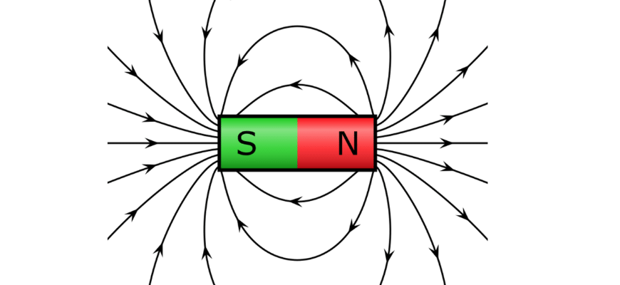
Every magnet has a North and South pole; like poles repel and opposite poles attract.
This diagram shows the familiar shape of the field around a bar magnet. Once again, the density of field lines represents the strength of the field, which is given the symbol \( B \) and is measured in units of tesla \( (\text{T}) \).
The field lines always point away from the North pole and into a South pole. Remember, North and South are separate from positive and negative charge.
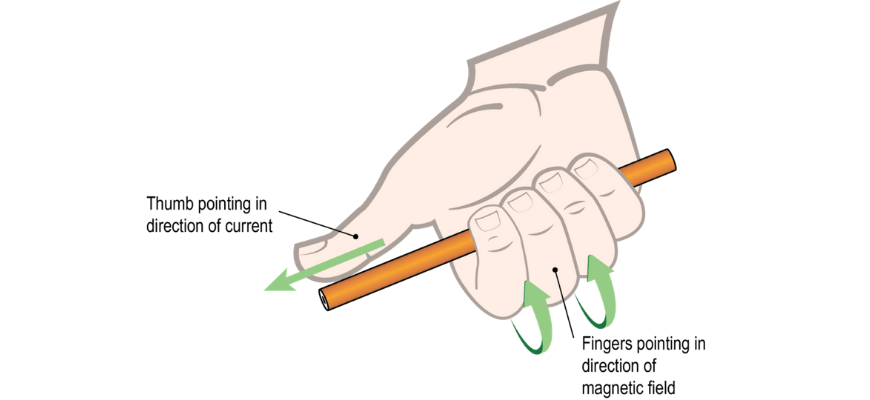
This module adds to your knowledge by introducing an important connection between electricity and magnetism: magnetic fields are not just created by magnets, but also by current-carrying conductors – such as the wires in a circuit!
When current flows through a wire, it creates a magnetic field consisting of concentric field lines around the conductor. The direction of the field lines can be predicted using the Right Hand Grip Rule, illustrated here:
The strength of the field \( B \) is given by
\begin{align*}
B = \frac{\mu_0 I}{2 \pi r}
\end{align*}
Where:
This makes it possible to construct an electromagnet, a device where the magnetic field can be switched on or off.
To do this, the wire is wrapped around several times to create a solenoid; its field direction can then be predicted using the Right Hand Coil Rule.
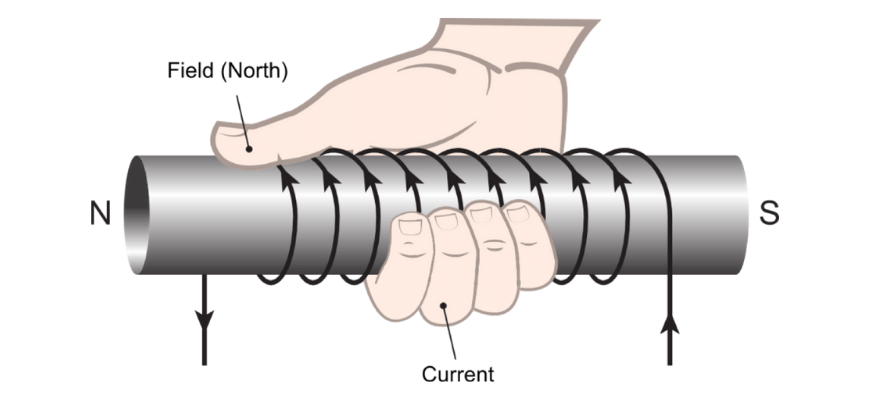
Grasp the loop so that the curled fingers of the right hand point in the direction of the current. The thumb of the right hand points in the direction of the magnetic field within the loop of wire.
We generally assume the magnetic field inside a solenoid is constant. It is given by the amount of the current \( I \) and the geometry of the solenoid:
\begin{align*}
B = \frac{\mu_0 N I}{L}
\end{align*}
Where:
In Module 6 next year you will learn more about the connections between electricity and magnetism.
You will explore the effects that both electric and magnetic fields have on charged particles and current-carrying conductors.
As you study the theory of electromagnetism, you will also learn how simple electrical devices such as motors, generators and transformers work – maybe you will even get to build your own!
© Matrix Education and www.matrix.edu.au, 2025. Unauthorised use and/or duplication of this material without express and written permission from this site’s author and/or owner is strictly prohibited. Excerpts and links may be used, provided that full and clear credit is given to Matrix Education and www.matrix.edu.au with appropriate and specific direction to the original content.